Bojian Wu
ustcbjwu [AT] gmail.com
Chinese Academy of Sciences (CAS)
Week 4
Practical Ray Tracing of Trimmed NURBS Surface[Download]
In BRL-CAD, they use algorithms mentioned in this paper to do ray tracing of trimmed NURBS surface, actually in brep.cpp, functions whose name starts with 'utah_' is an implementation of the algorithms proposed in this paper.
Here I will give a brief introduction of it as follows.
Generally speaking, it proposes a practical method suitable to implementation in general ray tracing programs. Besides, it also supports the direct use of untessellated trimmed NURBS surfaces. The key idea is outlined as follows(taken from the paper).
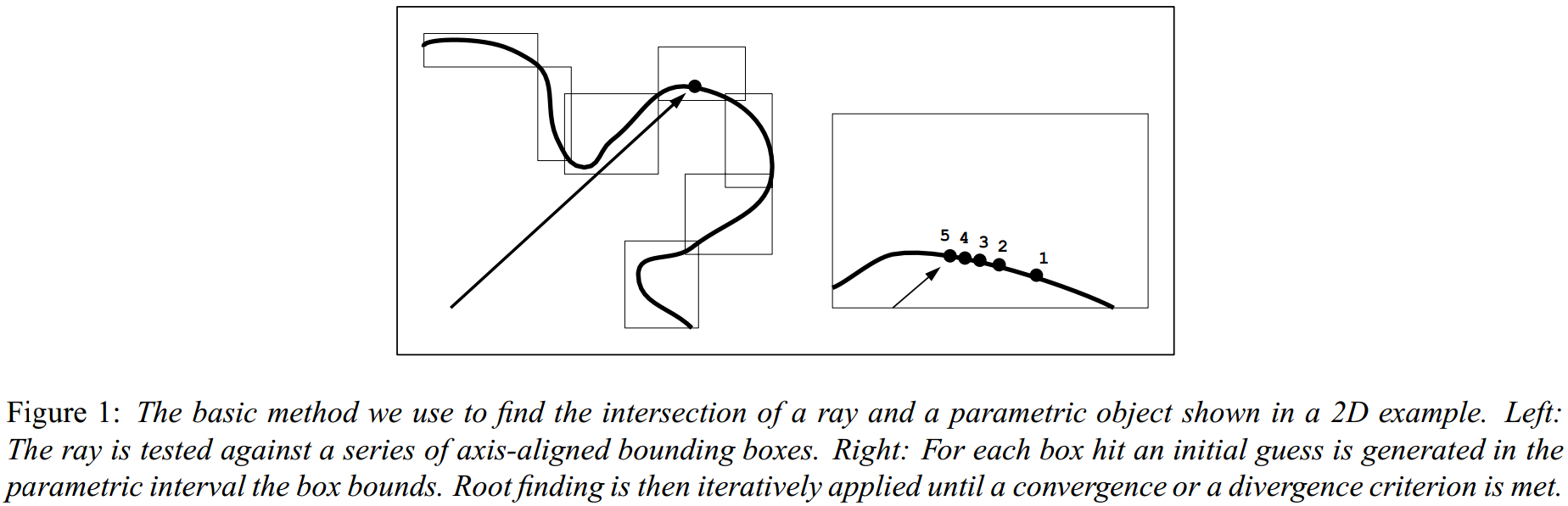
The simplified pipeline for computing ray-NURBS intersections usually has three main components: flattening, generating the BVH(Bounding Volume Hierarchy) and root finding.
By the way, in order to accelerate the ray-NURBS intersection test and enable precise computation, we can also partition the ray into several pieces and use bounding box of each ray partition to do intersection test with bounding box of each node of BVH. By doing this, we can improve the precision of initial guess of intersection point.
Current status of NURBS ray tracing
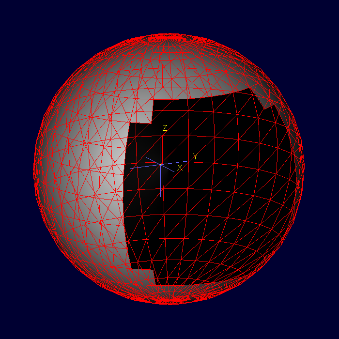
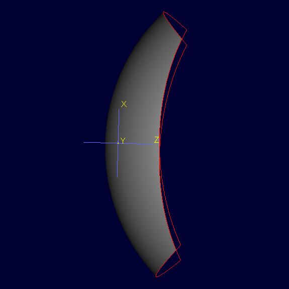
In order to figure out current status of NURBS ray tracing, I design several examples to make comparisons between B-rep and BoT as follows, because what I want to do is trying to keep behaviours occurred both in B-rep and BoT more consistent.
Generally speaking, I have four groups of examples below which can always be summerized as ray traing of open/closed mesh with ray starting from inside/outside of the mesh.(To be more precise, when the mesh is open, we think if the starting point of ray is inside the bounding box of mesh, then the ray starts from the inside.)
I have made a conclusion with brief analysis of the all the results.
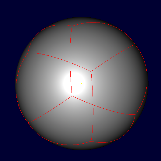
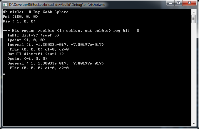
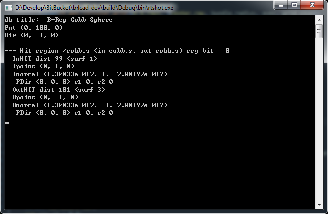
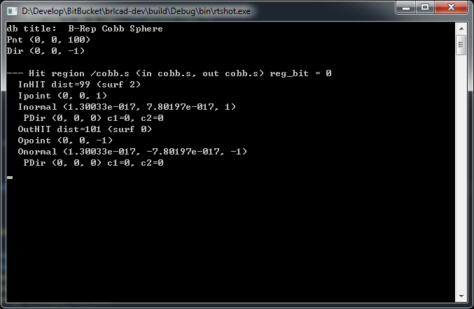
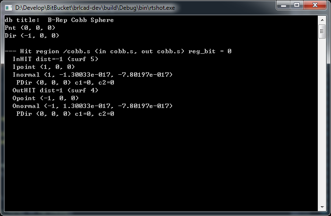
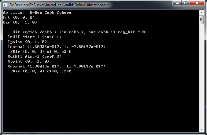
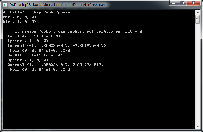
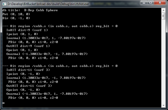
Let's start from the simple case. If the mesh is closed(see Table 4-3 and 4-4), not matter in surface mode or plate mode, all the behaviours seem to be similar by comparing B-rep and BoT, so in our later implementation, we do not need to pay much more attention here if the mesh is closed.
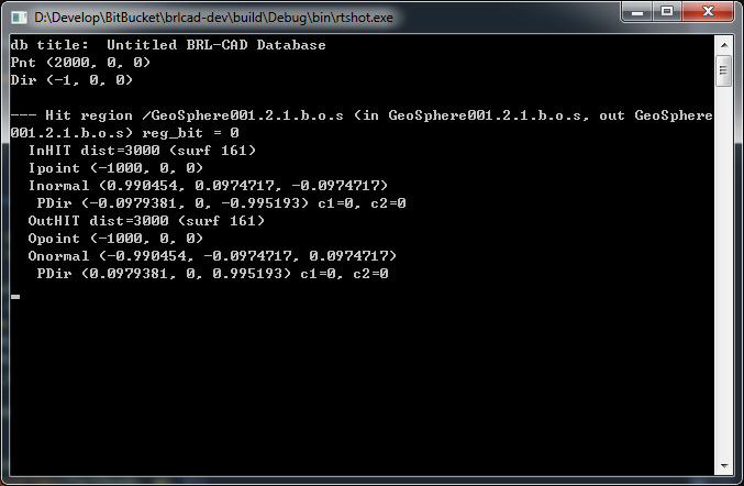
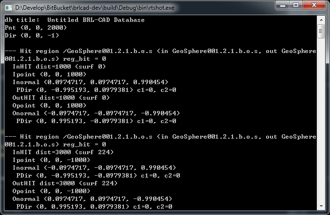
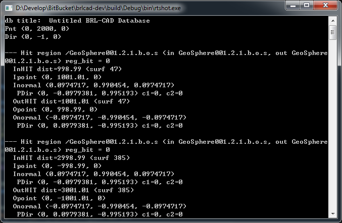
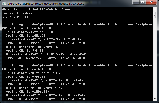
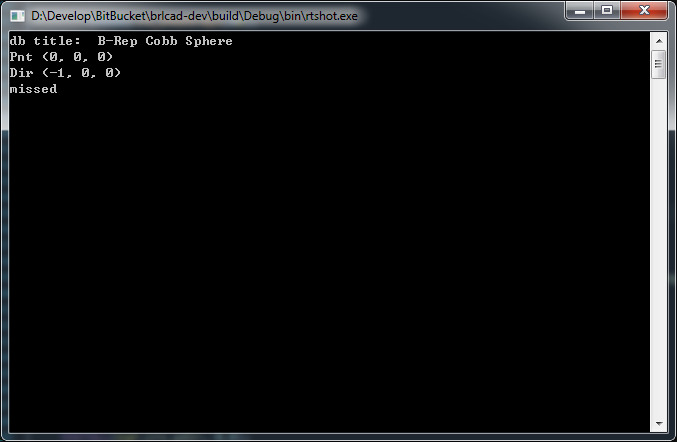
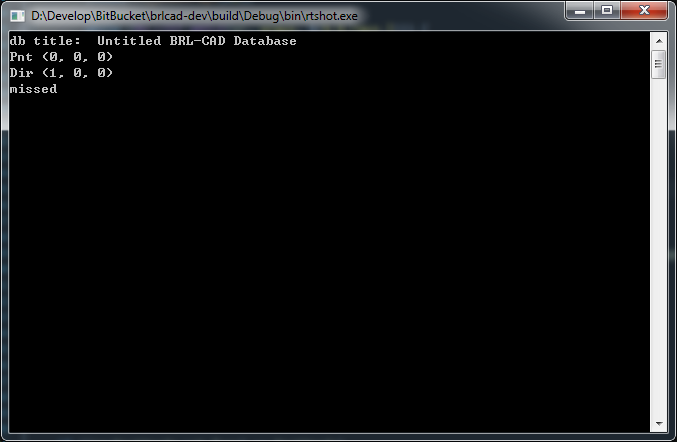
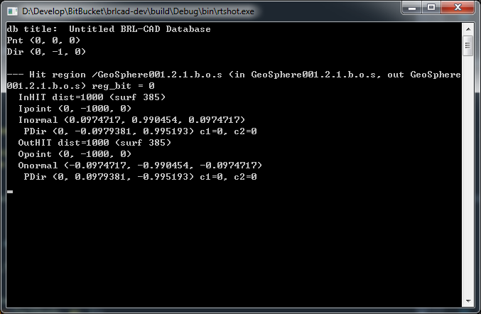
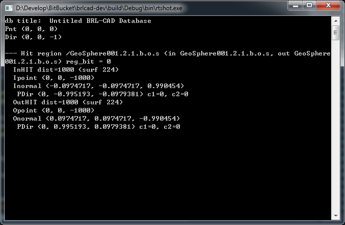
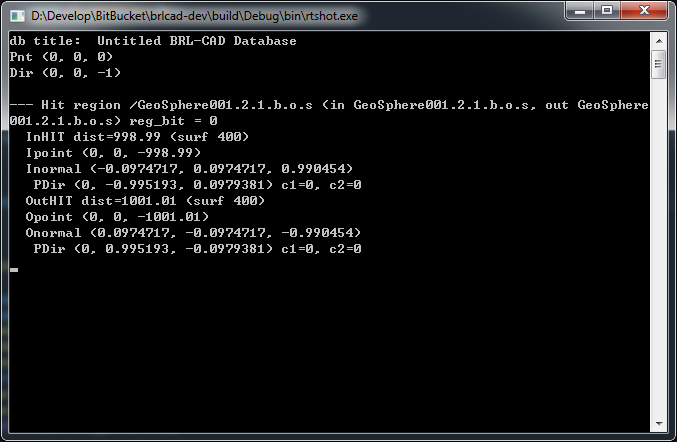
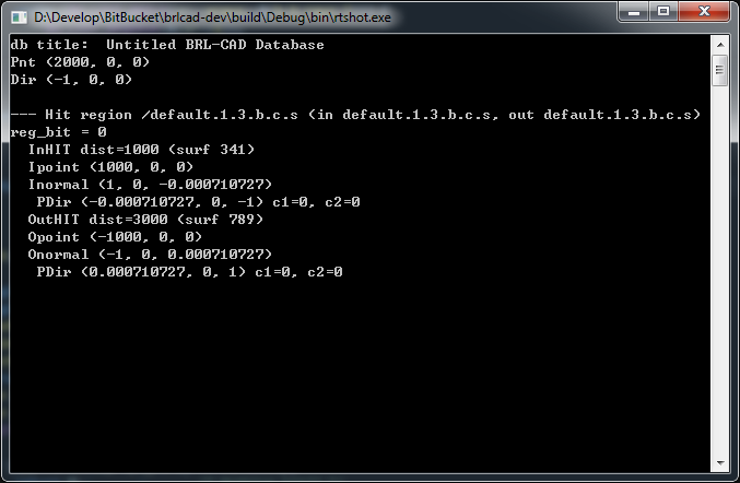
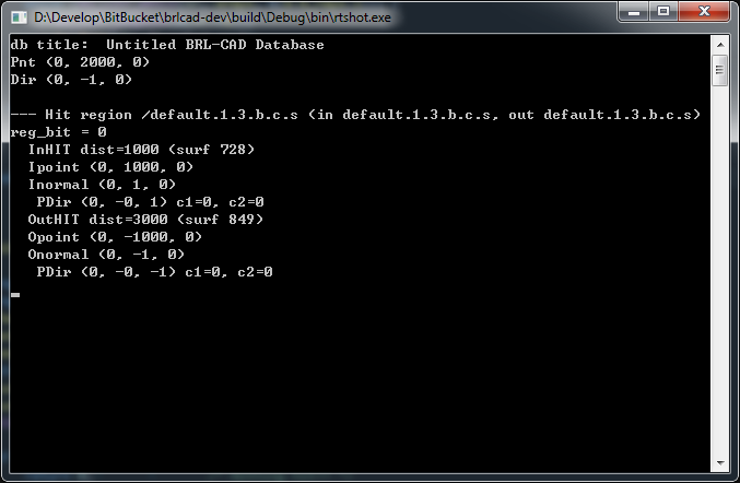
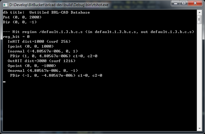
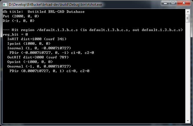
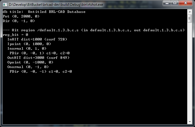
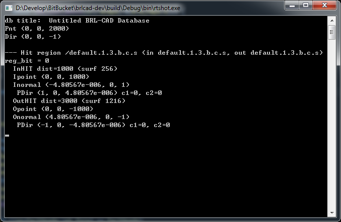
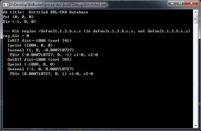
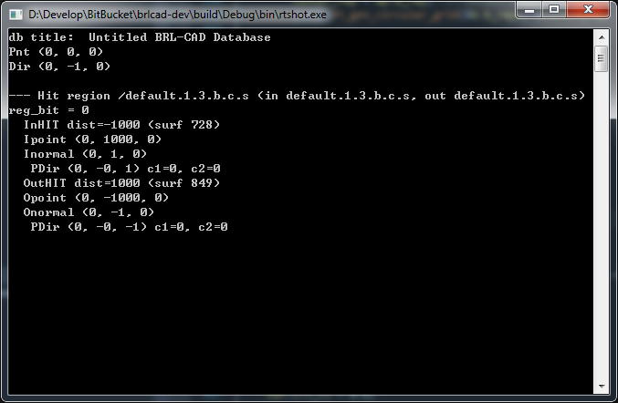
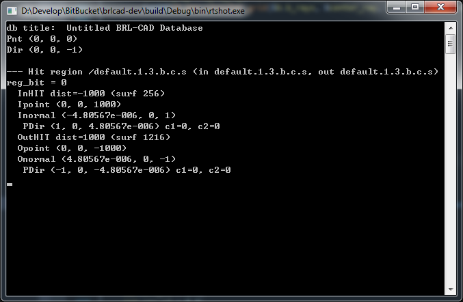
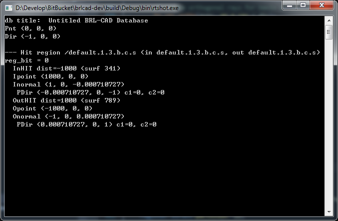
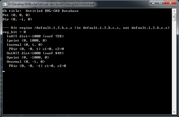
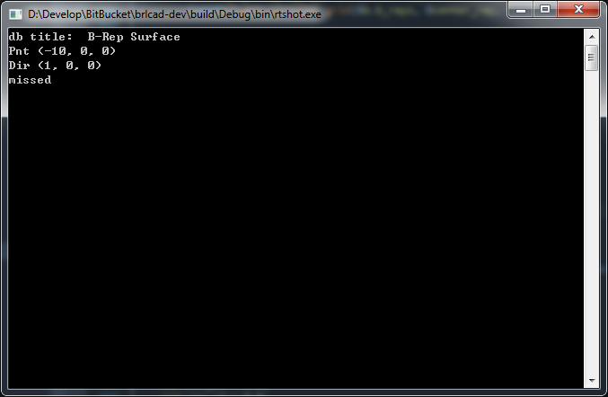
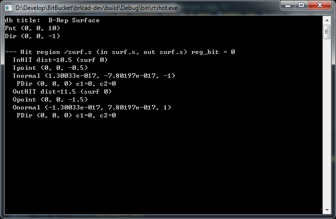
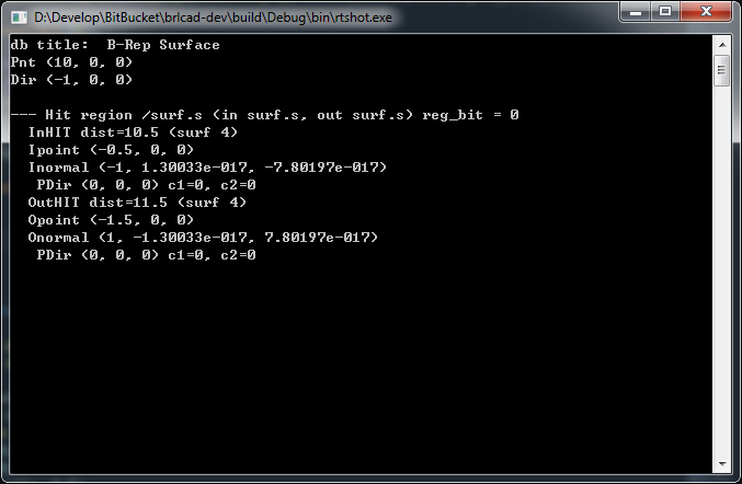
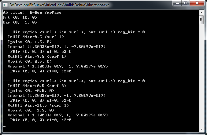
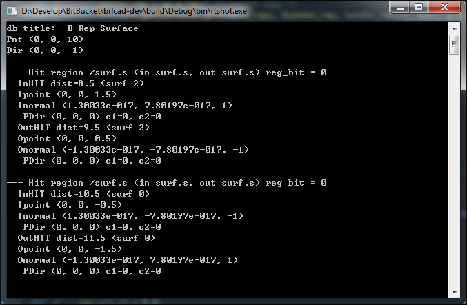
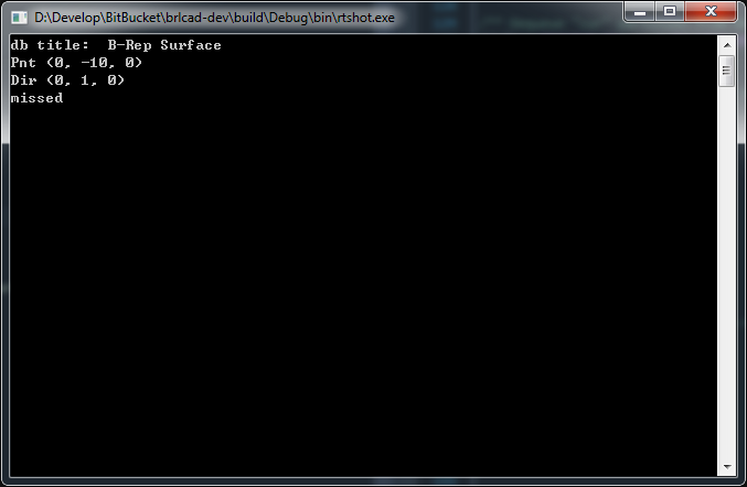
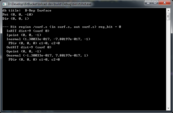
Then if the mesh is not closed, things are different. For B-rep, currently, it will only report a pair of hit points which are located in different positions on the mesh. Please refer to the 'Shot along Y axis' and 'Shot along Z axis' result in Table 4-1 and 4-2 for a more intuitive understanding. But if we only have one hit point(you can get it by debugging the program and following the code step by step), like 'Shot along X axis', it will report a miss, however you should know that the ray actually hits the surface, so the result here is not so reasonable. Basically, for BoT, both in surface mode and plate mode, each hit will contain both in point and out point even they are the same but with different normal. So in our real implementation, we need to pay more attentions to this part and try to make it more reasonable.
| Model | Shot along X axis | Shot along Y axis | Shot along Z axis |
|---|---|---|---|
 (B-rep) |
 |
 |
 |
 (BoT) |
 |
 |
 |
(BoT in plate mode) |
 |
 |
 |
| Model | Shot along X axis | Shot along Y axis | Shot along Z axis |
|---|---|---|---|
(B-rep) |
 |
 |
 |
(BoT) |
 |
 |
 |
(BoT in plate mode) |
 |
 |
 |
| Model | Shot along X axis | Shot along Y axis | Shot along Z axis |
|---|---|---|---|
 (Closed B-rep) |
 |
 |
 |
 (Closed BoT) |
 |
 |
 |
(Closed BoT in plate mode) |
 |
 |
 |
| Model | Shot along X axis | Shot along Y axis | Shot along Z axis |
|---|---|---|---|
(Closed B-rep) |
 |
 |
 |
(Closed BoT) |
 |
 |
 |
(Closed BoT in plate mode) |
 |
 |
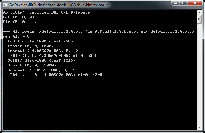 |
Plate Mode NURBS ray tracing
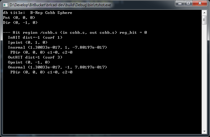
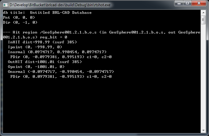
Here, I will show some results below. As we can see, for open mesh in plate mode, the result is satisfactory at present by comparing with the results shown in Table 4-1 and 4-2.
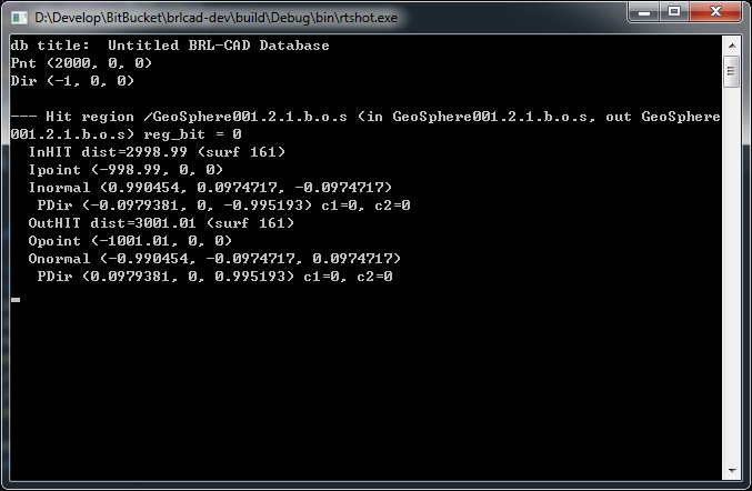
Basic idea here is to seperate one hit into two hit points including in one and out one no matter it is in surface mode or plate mode if the mesh is open. In surface mode, the in and out point should be the same one but with opposite normal direction. But in plate mode, things change differently, we need to offset the in/out hit distance according to the thickness value assigned to the mesh. In my implementation, I center the real hit point and move the in hit point along the reverse incident shooting ray direction with half thickness value and vice verse for out one.
There is a delimma that encounted in Table 4-1, that is, in the old implementation, if we only have one hit point, it will report a miss, apparently it is un-reasonable, so in my new implementation, it will report a hit with two hit points even though they are the same one but different normal direction. This should be more acceptable for plate mode ray tracing.
| Model | Shot along X axis | Shot along Y axis | Shot along Z axis |
|---|---|---|---|
 |
 |
 |
 |
|
 |
 |
 |
| Model | Shot along X axis | Shot along Y axis | Shot along Z axis |
|---|---|---|---|
|
 |
 |
 |
|
 |
 |
 |