Bojian Wu
ustcbjwu [AT] gmail.com
Chinese Academy of Sciences (CAS)
Week 7
Transforming old B-rep model into my new format
In my lastest implementation, I have integrated the plate mode(thickness value) information into B-rep model, but to this end, I need to set an extra flag to indicate whether the model has thickness value or not, so compared with the old B-rep representation, the lastest format is not so compatible with the old one, this is why I need a tool to transform between these two different formats.
Here is the source code of this simple tool.
Short plan for further testing of plate mode raytracing
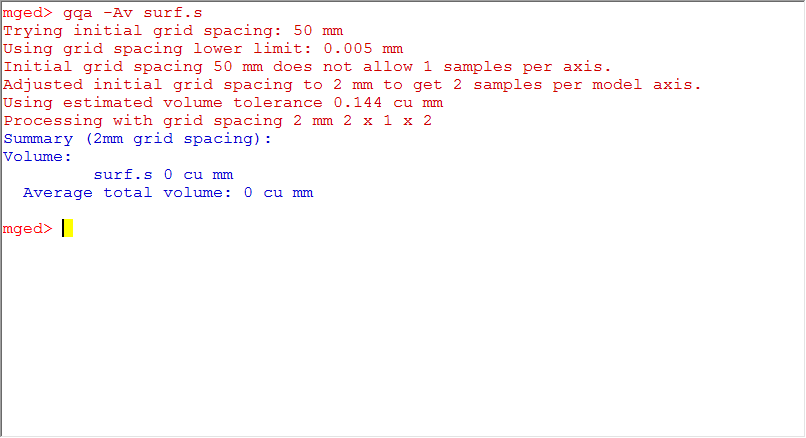
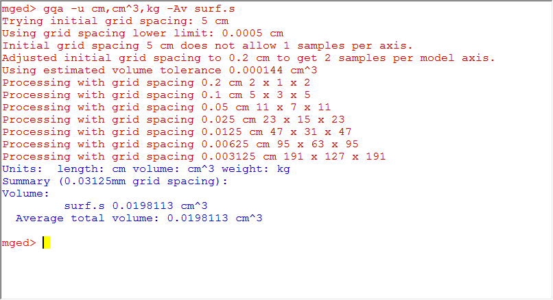
Issues when using *gqa*?
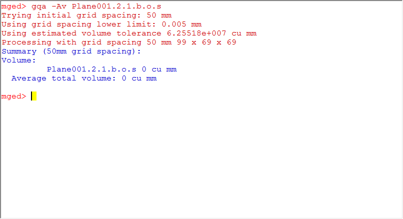
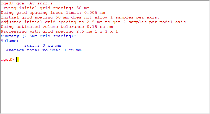
PROBLEM 1: I design a single plane(BoT with thickness) as input and try to compute its volume, but the program does not work and response, no matter what grid size I set, it always stuck in searching an optimal grid size to guarantee at least 1 samples per axis. What I think is that, actually, the single plane always does not have thickness in one dimension(for example, if the plane spans at x-y, and it do not have thickness along z axis), so if the ray comes from that direction, it will not hit the plane, never to say an optimal grid size, so the program can not proceed. This is just my inference, for more, I need to confirm with others or read the code.
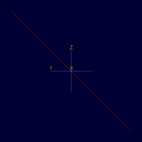
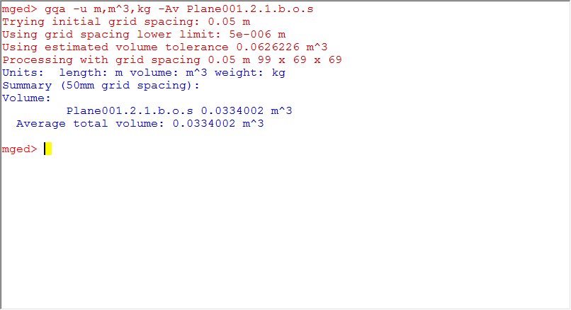
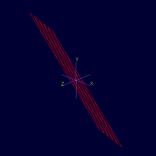
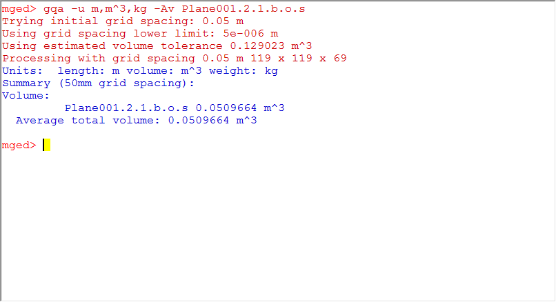
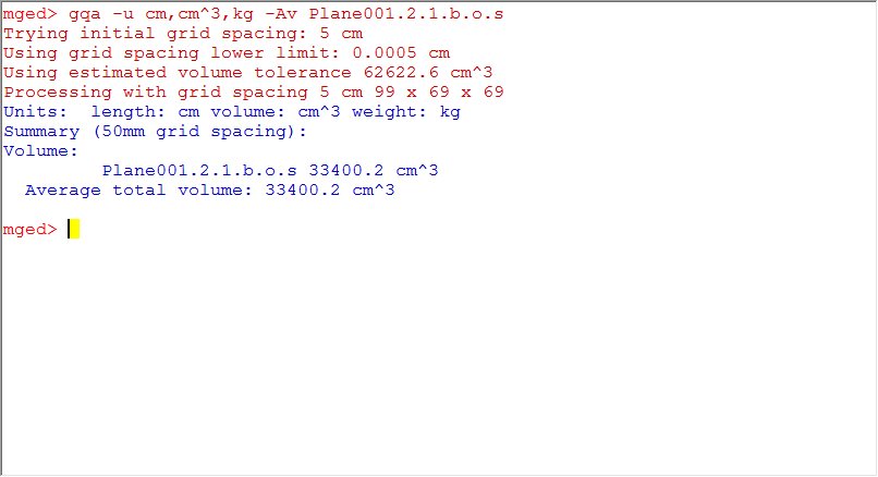
PROBLEM 2: In order to solve the single plane problem described above, this time, I rotate the plate in two ways(along x axis and randomly posed) as shown below, but the weird thing happens, the two volumes are totally different? How could it be, the same plane in different position and rotation but same thickness value, while the volume is different?
NOTE: I have figured out why it happens. Actually, it is not related to the BoT but the type of plate mode it specifies. In my examples, the type is 'plate', that is to say, when doing raytracing, we still need to consider the oblique angle when computing the hit distance and points. In constrast, there is a type called 'plate nocos', it just offset the hit point along the ray direction without any further computation. Let us get back to the problem. When rotating the models, the oblique angle should change accordingly, so the hit distances differ each other, then the volume calculated also varies.
 |
 |
 |
 |
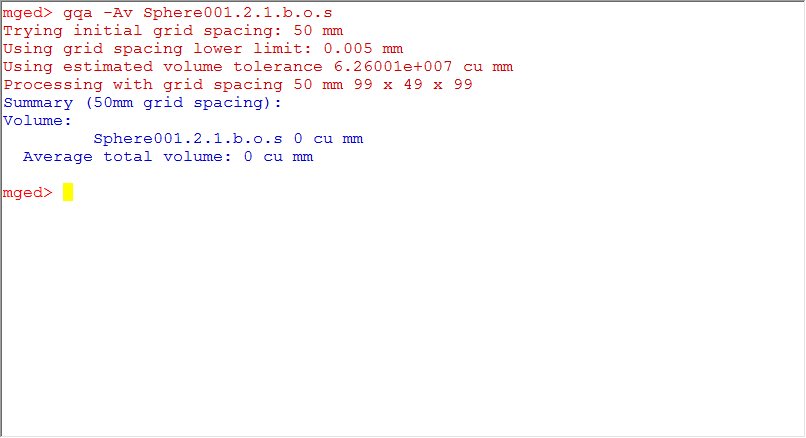
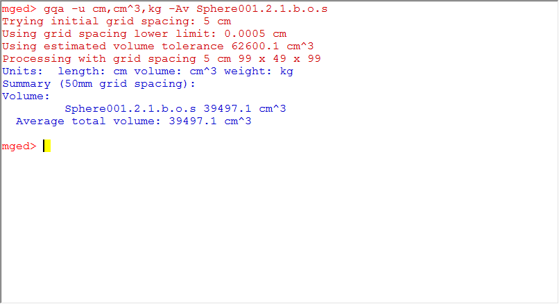
Examples by using *gqa* to compute the volume?
PLEASE NOTE THAT All the BoT models are generated in 'plate' type but not 'plate-nocos', I have already updated all the lastest results in next week's report.
I will separate this part into several sections, because *gqa* does not work correctly on single plane as illustrated above, so I will not test it but start with arc surface(1/2 of a sphere).Single plane
| Surface Type | Model | Normal Mode | Plate Mode (thickness = 2) |
|---|---|---|---|
| BoT | 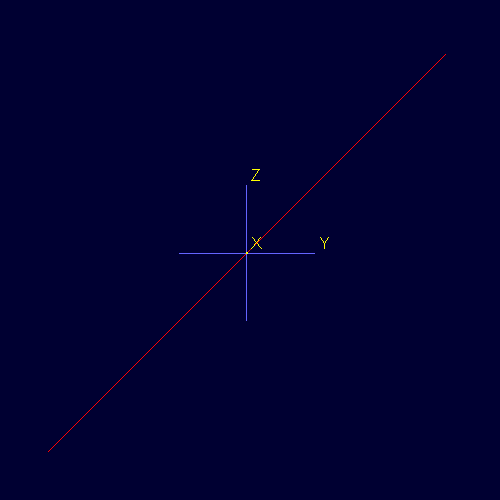 |
 |
 |
| B-rep |  |
 |
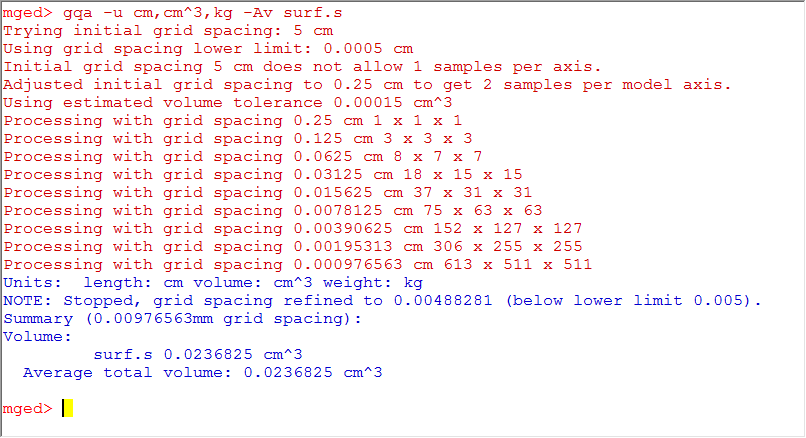 |
Hemisphere
| Surface Type | Model | Normal Mode | Plate Mode (thickness = 1) |
|---|---|---|---|
| BoT | 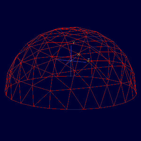 |
 |
 |
| B-rep | 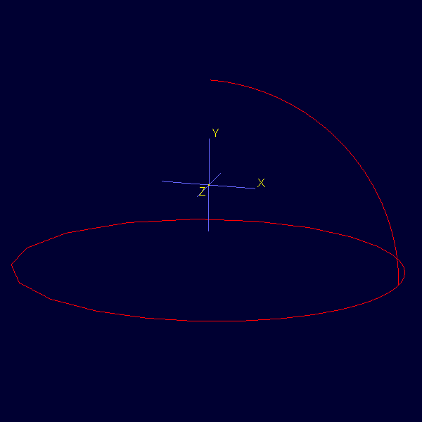 |
 |
 |